Planning around the light
Spherical Crystallized Light depends on a complex combination of reflection and refraction. The light within the crystals can only be seen from a limited range of angles, so the placement of the installation directly affects what visitors can see.
I was responsible for spatial planning, CG simulation and visual evaluation. I developed shaders and scripts to recreate the optical behavior in CG, then used the model to study sightlines and plan the arrangement. The aim was to give visitors of different heights a good view from a range of distances and positions.
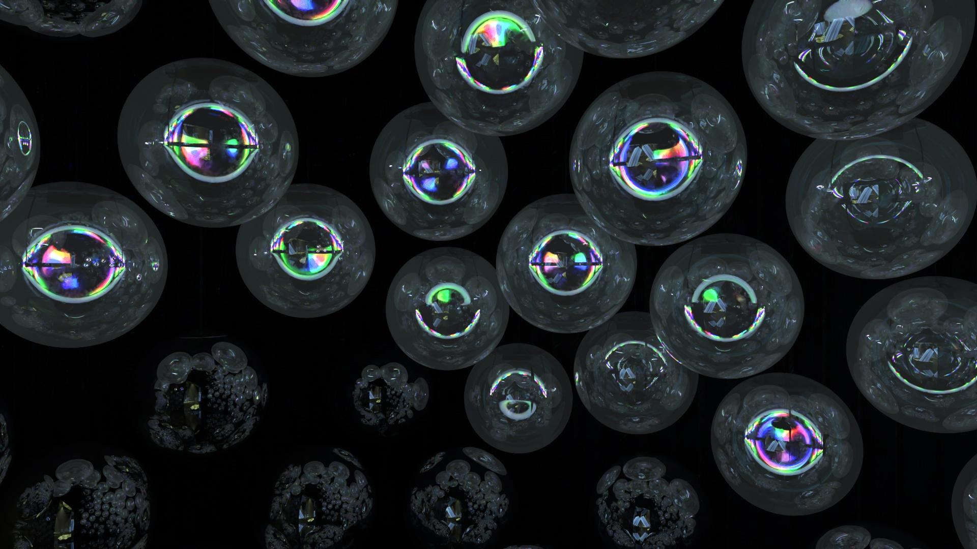
Recreating the optics in CG
I developed custom shaders and scripts to recreate the installation’s reflection and refraction. With the optical behavior included in the room model, I could compare where the internal light appeared as I changed the viewing position and the placement of the elements.
Open on YouTube for the full 360° experience. Drag the view to look around.
Working within the space
The layout had to work within power-supply, fire-safety and cable-routing constraints while keeping the crystal light visible. I considered these practical limits together with the viewing angles, using the CG model to evaluate where the elements could be placed.
I checked the view through the entrance as well as positions inside the room. This meant looking beyond a single camera view: a placement that worked from one distance or height also needed to be considered from closer, farther away and at other eye levels.
Checking different heights and positions
I simulated sightlines for visitors of different heights, at several distances and positions inside and outside the room. I used these comparisons to adjust the arrangement so that the crystal light would be visible across a wide range of viewing positions.
For the section studies, I set eye height at 100 mm below body height and compared the original LED height with increases of 100 mm and 200 mm.
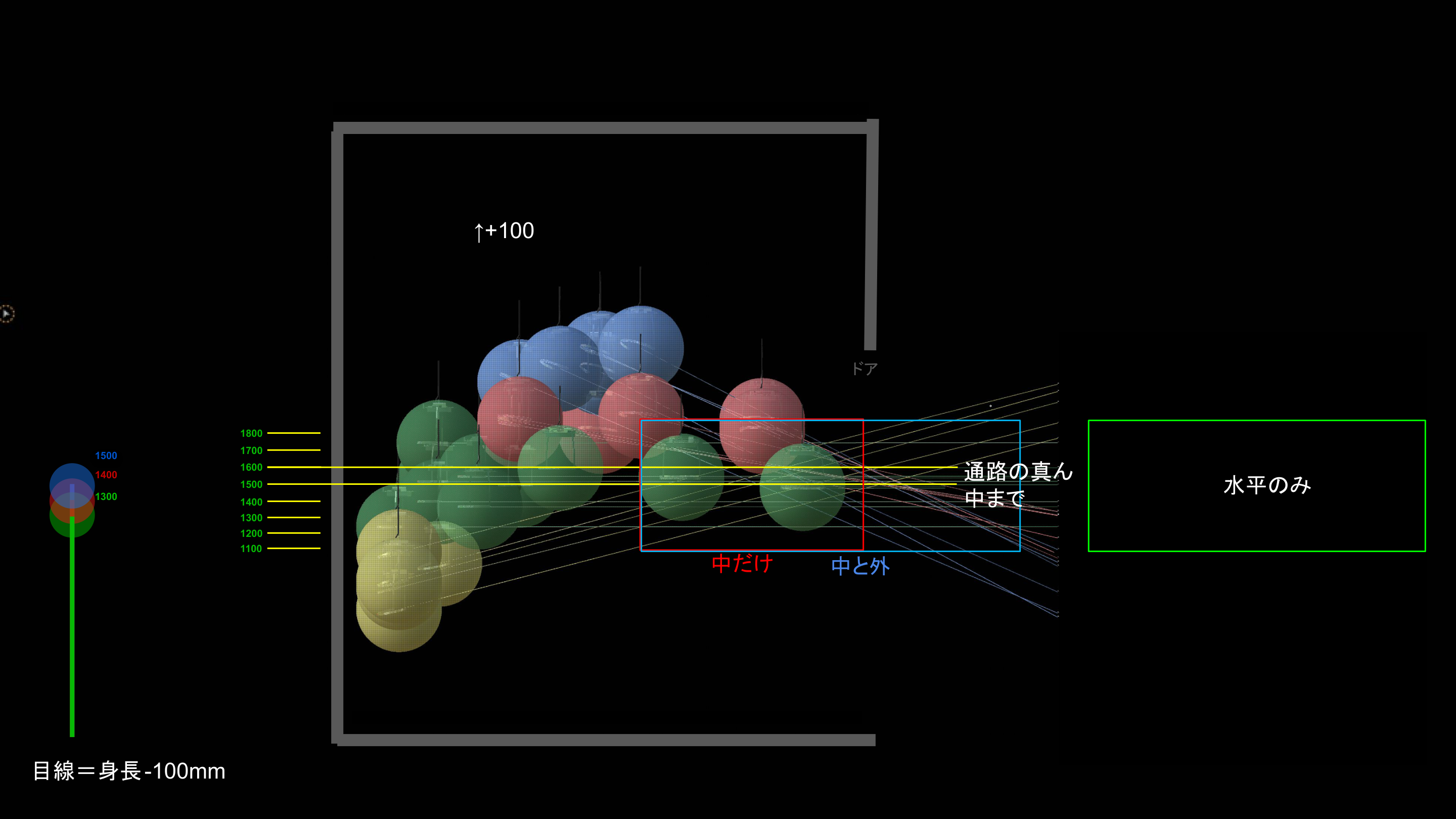
Adjusting height and light direction
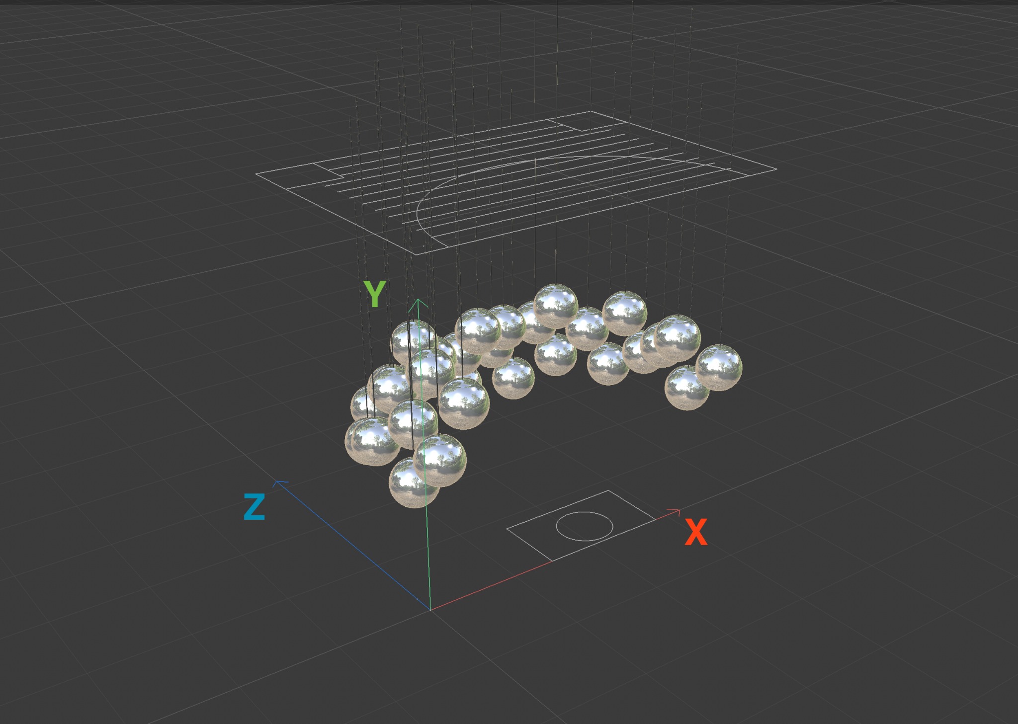
I used a 30-sphere arrangement as a base and compared its original height with versions raised by 100 mm and 200 mm. Each sphere had a defined position, which allowed me to make small adjustments and compare their effect from the same viewpoints.
I also tested downward, horizontal and upward LED directions alongside spheres without LEDs. Color-coded layouts helped me work through placement and light direction together, including elements moved between the floor and the suspended arrangement.
Balancing floor and suspended elements
I explored different combinations of floor and suspended spheres, including additional floor lamps, non-light-emitting elements and clustered hanging arrangements. Moving or adding a sphere changed both the spacing between objects and the distribution of light across the room.
I compared these versions from three exterior and three interior cameras. The entrance views let me judge the composition within the opening, while the interior views showed the arrangement around the visitor. I kept the camera positions fixed so I could concentrate on the changes to the spheres.
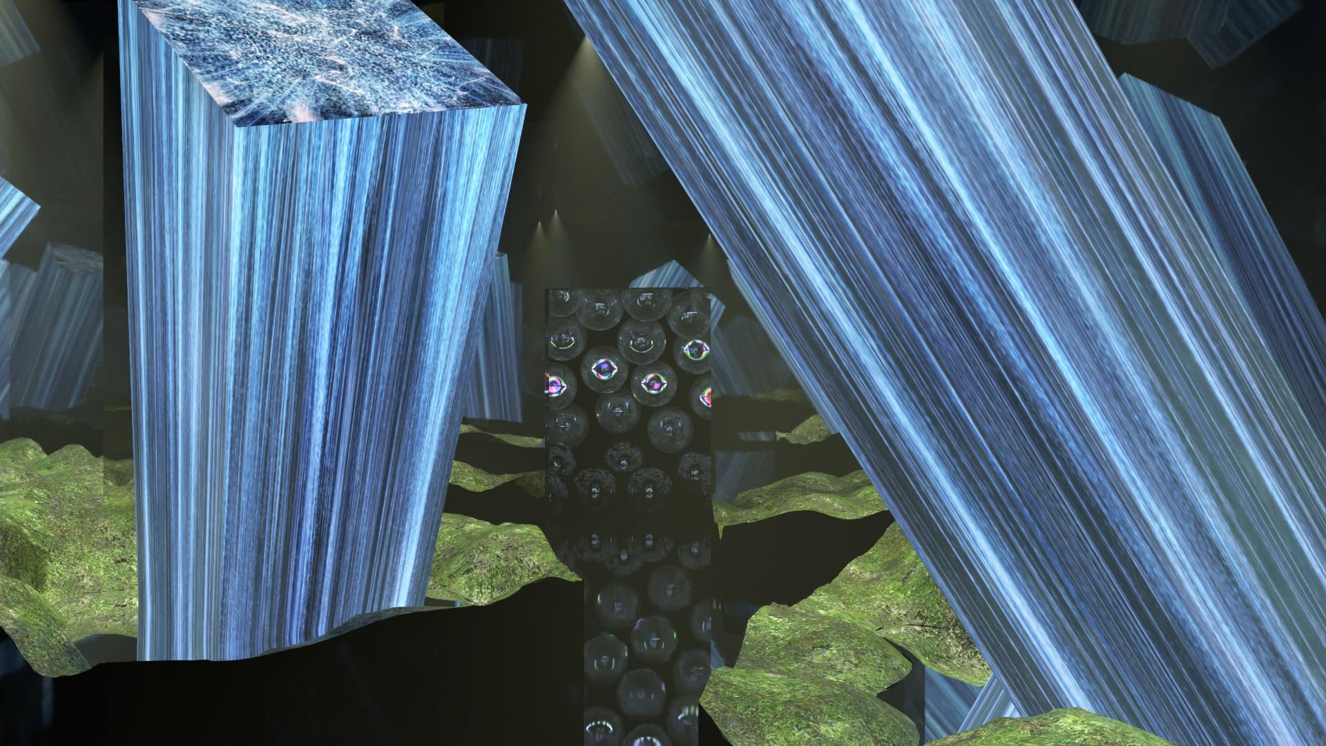
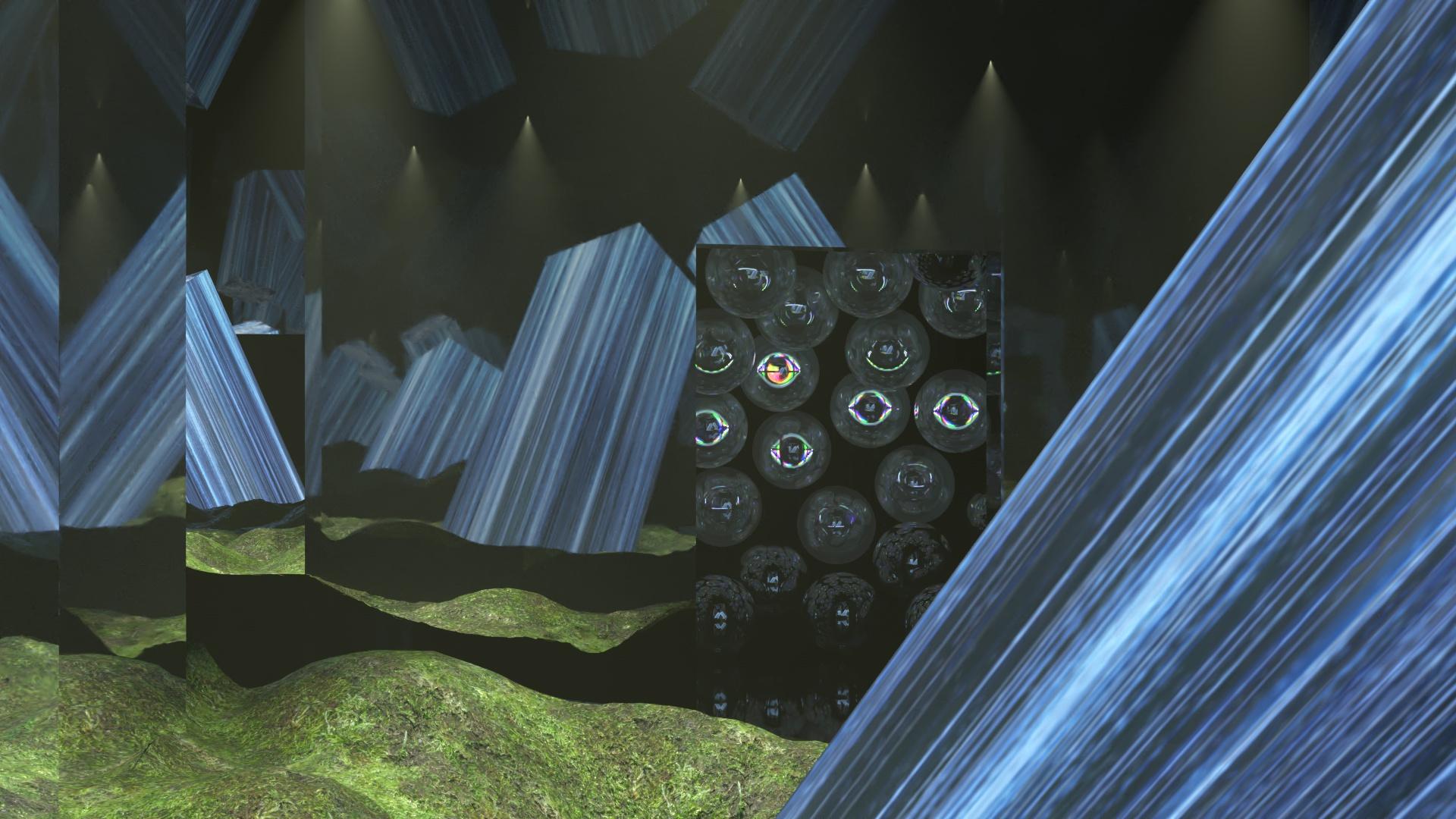
Comparing internal components in CG
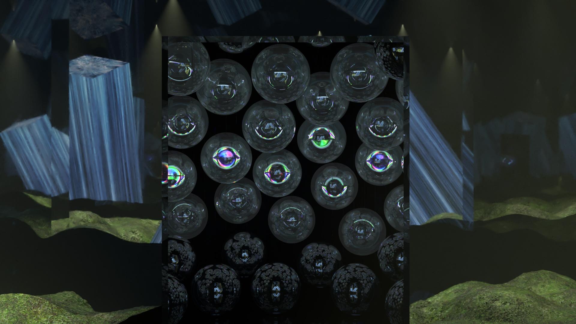
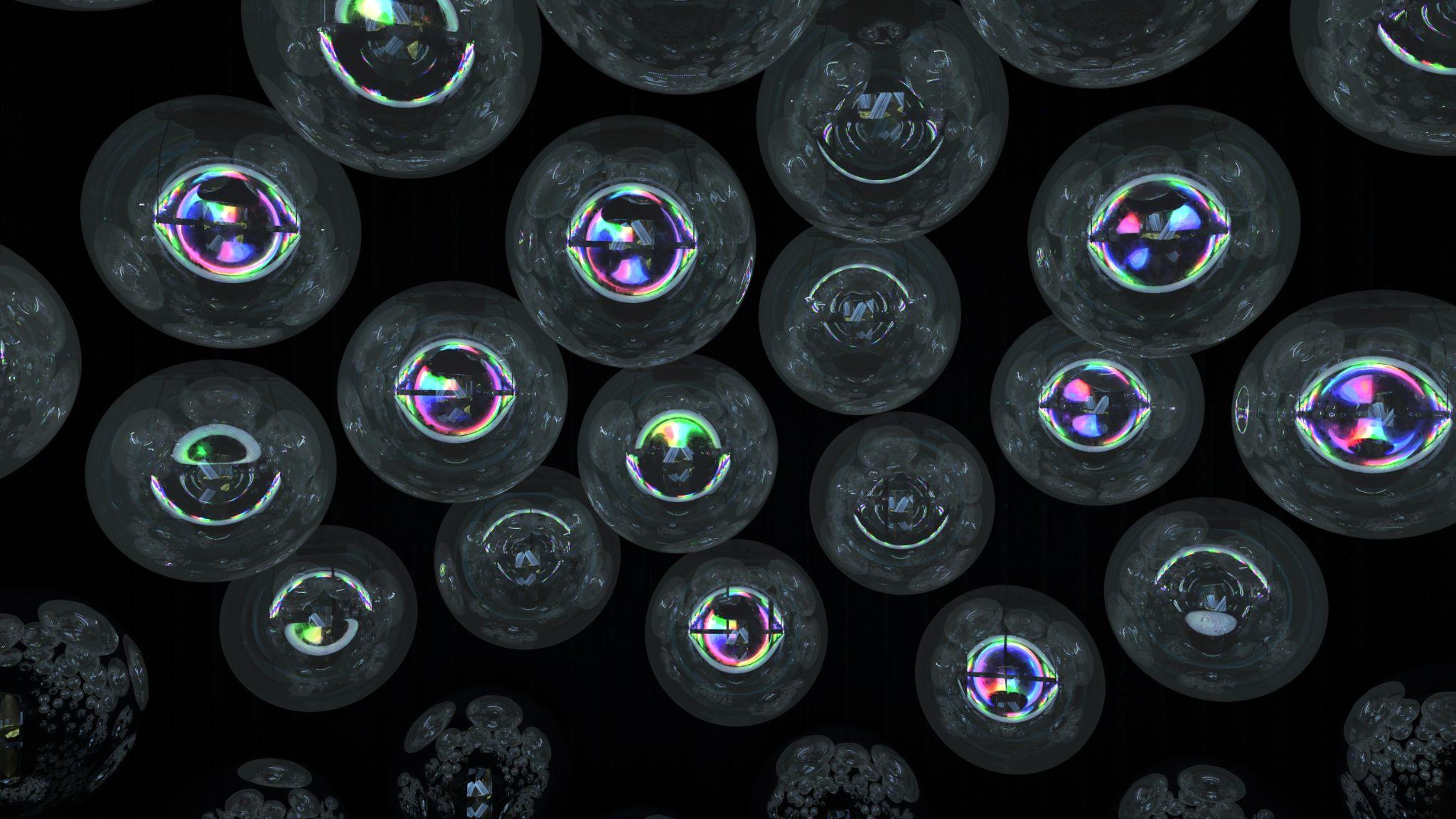
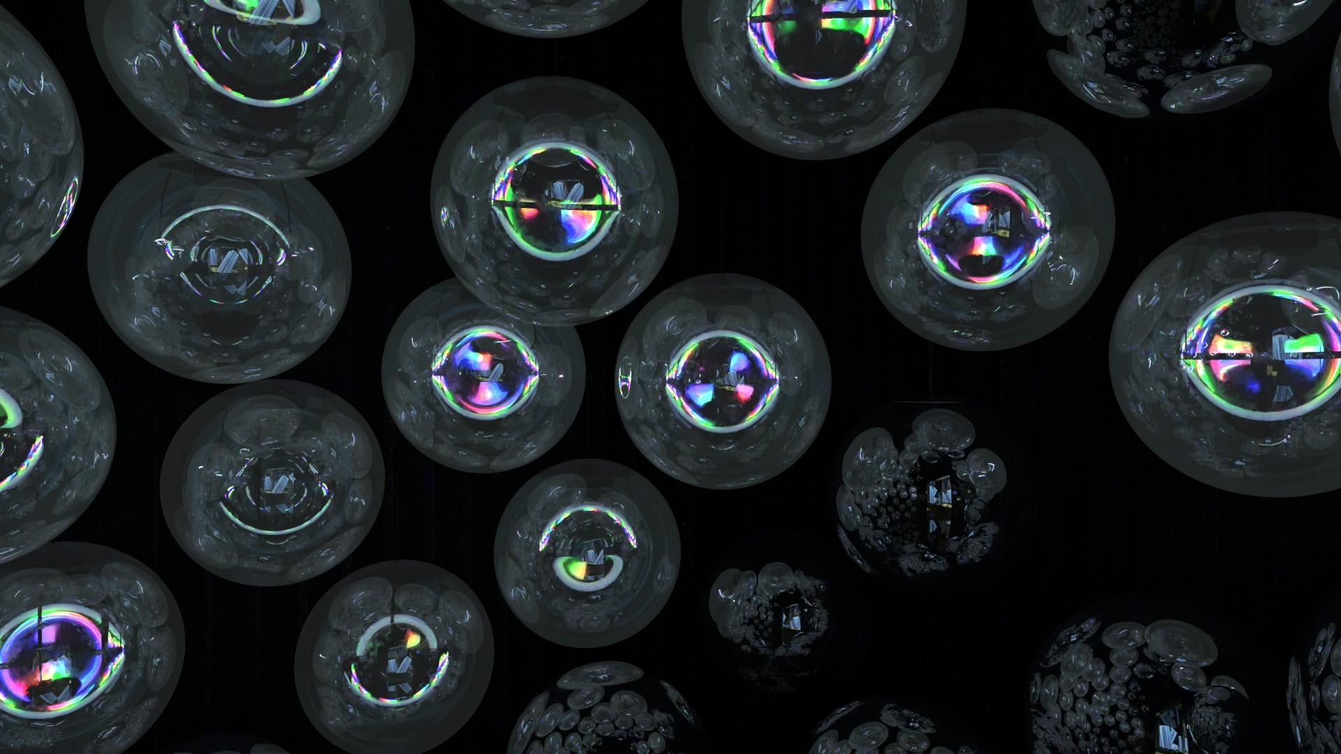
I used CG simulations to compare different combinations of internal optical components and the light patterns they produced. All three videos below are CG simulations.
Reviewing the view around the visitor
I used 360-degree CG views to review the arrangement around a visitor. These views brought together the element heights, positions and light directions, allowing me to assess the experience beyond a single fixed image.
These are 360° CG simulations. For the best viewing experience, open them in YouTube and drag the view to look around.
Open on YouTube for the full 360° experience. Drag the view to look around.
Open on YouTube for the full 360° experience. Drag the view to look around.
Placement drawings
The placement drawings record X, Y and Z coordinates in millimeters for each sphere, together with its LED direction.
Artwork by teamLab. My contribution: spatial planning, CG simulation and visual evaluation, including custom shaders and scripts for optical simulation.